Pavingstones Sold. Over 3 BILLION!
INSTALLATION INSTRUCTIONS
Need a Professional Installer? Find a Professional Installer
For your convenience, do-it-yourself installation instructions are available for:
Do-It-Yourself Step-By-Step Installation Instruction Video
For additional information, visit your local Authorized Cambridge Distributor.
A Basic Interlocking Pavingstone System
|
EQUIPMENT LIST 1 Pair Gloves & Safety Glasses Carpenter’s chalk line Stakes Spade Stone cutter or masonry saw Plate compactor 8-10', straight 2"x4" yellow pine (2) 8' lengths of 1 1/2" O.D. PVC pipe Nylon mason string Tape measure Broom Line Level |
 Modified Herringbone Pattern |
 STEP 1-PREPARATION STEP 1-PREPARATION
|
 for
a 1" drop every 8'. Re-adjust the string lines to follow
slope marks. The string line represents the surface of the
completed job.
for
a 1" drop every 8'. Re-adjust the string lines to follow
slope marks. The string line represents the surface of the
completed job.
STEP 2-EXCAVATION
- Skim last 1/2" off with spade to leave soil undisturbed.
- Use chart to determine depth and gravel/sand requirements:
STEP 3-BASE
- Fill in the excavated area with the quarry process gravel, flattening, compacting and sloping. Use the 2x4 and cross string lines as a guide to assure a perfect base installation. Proper compaction and a smooth pitched surface base is vital.
- Install a curb or edge restraint to prevent spreading of the pavers.
- To determine where you want to install your edge restraint, lay a row of pavers with manufactured edgers, when available, from one side of the area to be paved to the other. Position your curb so that you maximize the use of whole pavers and minimize the number of stones you need to cut. Measure this distance and transfer the measurements to the curb area. Position your Pave Edge restraint and nail it into the aggregate base.
- Add the coarse sand and smooth
it out (do not compact) using the PVC pipes as
1 1/2" guides or rails and the 2x4 board. Do approximately 8' sections and be sure to lay pavers before preparing the next section of sand. Use a trowel to fill in the gaps left behind by the pipes after you remove them. Do not walk on or disturb the freshly placed sand.
- Lay the pavers on top of the smooth sand, beginning at the right angle. There are many pattern possibilities with Cambridge... ask for our DesignScaping pattern sheets.
- Each Cambridge paver is manufactured with a spacer bar to assure constant joint widths, this allows the sand to fill the joints.
- Just hold a paver so the bottom 1/4" to 1/2" clicks against the top edge of the paver already in the sand. Release your grasp dropping the paver directly downward.
- Use additional string lines to insure straight paver joints.
- Check that the rows of pavers are straight every 3' by running a string line along the front of the rows - making sure each paver touches the string.
- Always install pavers working off multiple cubes, if project allows. Remove paver from the cubes by bands vertically.
- Once you have laid all the pavers that will fit your area, you may need to cut some to fit.
- Use your stone cutter for simple cross cuts or a power driven masonry saw for angled cuts.
- Using the plate compactor, make two passes over the installed pavers. This will seat the pavers, forcing sand up between the joint and completing the interlocking effect of the Cambridge Pavingstone System.
- All TEXTURED Pavers: As a precaution against scuffing: when compacting all textured products a bolt-on urethane protection mat should be used. As an alternative, place a heavy-duty geotextile (filter fabric) over the pavers prior to compaction.
- Sweep more sand over the surface until all joints are filled to the bottom of the chamfered edge.
- Compact again.
- Repeat process until joints are filled.
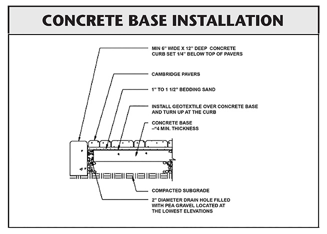
How To Install Your Cambridge Pavingstones System Concrete Base Installation
- Step 1. Preparation: Sketch a diagram of area to be paved. Square off a 90-degree corner. Set stakes for outside perimeters 6 inches away from area. Establish finished height and slope by setting leveled string lines. Allow 1-inch drop every 8 feet at sides for water runoff.
- Step 2. Excavation: Excavate (7 1/2 inches for patios and walkways/11 1/4 inches for driveways).
- Step 3. Base: Pour concrete slab (4" for patios and walkways / 8" for driveways).
- Step 4. Base Drainage: drill 2" diameter drain holes (weepholes) filled with pea gravel located at the lowest elevations. The amount of weepholes depend on the size of the project. Install Geotextile over concrete base and turn up at the curb.
- Step 5. Edging: Install your fixed edge restraint of concrete or Belgium block curbing.
- Step 6. Placing (Screeding) Sand: Add coarse C-33 sand and smooth out to a uniform 1 inch.
- Step 7. Pavers: Place Cambridge Pavingstones on the smooth sand in the desired pattern making sure joint lines are straight. A built-in spacer bar assures consistent joint width.
- Step 8. Cutting: Using a stone cutter or masonry saw, cut pavers where necessary to fit.
- Step 9. Compacting: With two passes of a plate compactor, seat the pavers by forcing sand up into the joints.
- Step 10. Sweeping/Final Compaction: Sweep additional sand into joints, compact again and repeat until all joints are filled.
- Note 1. Base thickness varies with traffic, climate, and sub grade conditions
- Note 2. Concrete curbs do not deflect to the same depth as Cambridge Pavers or existing asphalt. This detail is not recommend for other than low volume residential streets.
Special Notes:
How To Install Your Cambridge Segmental Retaining Wall System
 |
- Step 1 Excavation: Dig a trench roughly 8" deep and 12" wide.
Firmly compact until bottom is fairly level. Add 6" of 3/4" clean gravel and compact again.
- Step 2 Leveling Course: Add 1" of coarse C-33 sand into bottom of trench.
- Step 3 First Course: Place Cambridge wall units in trench touching each other
(textured face outward on single-face units). Keep all units level in all directions.
For straight walls, also use a string line.
- Step 4 Additional Courses: Stack staggered wall units on top stepping each new row back
approximately 3/4". In this type of gravity wall installation, weight and set back of the units provide
resistance. Backfill with 3/4" of clean granular fill and compact as each course is completed. To
prevent any granular fill or soil from passing through the system, a landscaping fabric can be placed
behind the wall units. Add cap units if desired.
Important Notice: A bolt-on urethane protection mat must be attached to the plate compactor as a precaution against surface scuffing on all pavingstones from The Sherwood and RoundTable Collections as well as textured pavingstones from The Renaissance Collection.
A Circle Design Kit
Circle Design Kits are available with ArmorTec from The RoundTable Collection and also tumbled-distressed from The Renaissance Collection.
Creating Fans using a Circle Design Kit
Cambridge Cutting Templates
(Available At Your Cambridge Distributor)
With only thirteen cuts per fan, four fans consisting of a center paver and six rings can be created from each Circle Design Kit. Each fan will measure 65”w x 37”d. One kit will also accommodate two half radius patterns that are necessary to complete the design. See C on Drawing No. 1: Fan Pattern Installation Detail below.
A fan design can be created from the six paver shapes included in the Cambridge Circle Design Kit. However, to place fans into a field of Cambridge Pavingstones, five of the shapes in the kit will require precision cuts. Five convenient cutting templates can be found on a separate sheet included in this instruction package. Cut out each template along the outer edge.
To achieve a proper fit where one fan meets another, mark the prescribed cuts by placing specific templates on top of the shapes that require cutting. See reverse side for instructions on using the templates.
Proper Installation Procedures
- Make sure that a properly compacted quarry process base and layer of screeded C-33 sand has been installed.
- Run first string line down the center of the laying surface. See Center Line No. 1 on Drawing No. 1: Fan Pattern Installation Detail.
- Run a perpendicular line across the front of the laying face. See Line No. 2 on Drawing No. 1: Fan Pattern Installation Detail. To square up string lines, start the 3-4-5 triangle at B on Drawing No. 1: Fan Pattern Installation Detail. Leave sufficient room for the border course between Line No. 2 and the edge restraint.
- Start the first fan. See A on Drawing No. 1: Fan Pattern Installation
 Detail. Follow instructions carefully, making sure that the appropriate pavers for each row are laid over Center Line No. 1. Note that this is the ONLY method that will maintain symmetry of bond lines throughout the pattern. Straying from lines could tighten one side of the pattern and open the other.
 - Run two additional string lines parallel with Center Line No. 1. Refer to Center Line No. 3 on left and Center Line No. 4 on right on Drawing No. 1: Fan Pattern Installation Detail. Repeat this step as many times as needed to fill the width of the laying face.
- Repeat Step 4 on Lines No. 3 and 4. Make sure that the radii of the outer fans meet. See Drawing No. 1: Fan Pattern Installation Detail.
- Fill in with a half radius against the lower concave radius of each fan starting with Ring No. 6. Work back to Ring No. 3 as needed. See C on Drawing No. 1: Fan Pattern Installation Detail.
Cutting and Feathering on an overlay of pavingstones
 Cut & Feather Technique For Driveway Overlays
Standard specifications for installing an interlocking pavingstone system over an existing asphalt or concrete driveway do not require a gravel base except where the driveway meets the street and/or garage apron. In these areas, a necessary amount of the existing material should be removed and replaced with a dense base of quarry process gravel that has been feathered to meet proper grade (3" minus at garage floor/3" minus at curb).
After ruts in the old asphalt or cracks in the old concrete have been filled with stone screenings, follow four simple steps to cut and feather points where the pavingstone system will meet the street, curb or apron. Signs of pumping areas in the asphalt should be addressed with standard vehicular base preparation. Here's how to achieve proper butting and grade:
Step 1. Locate 3" point between a level string line and the existing pavement. See Illustration A.
Step 2. Cut and remove asphalt or concrete between the 3" mark and the garage apron and/or curb.
 Step
3. Excavate to 11" minus and prepare 8" (two 4" lifts)
of compacted DGA (dense graded base) of quarry process. See Illustrations
B and C.
Step
3. Excavate to 11" minus and prepare 8" (two 4" lifts)
of compacted DGA (dense graded base) of quarry process. See Illustrations
B and C.
Step 4. Lay SRW® SS5 woven geotextile filter fabric over entire area of existing pavement and added base. The filter fabric will prevent the bedding sand from migrating into future cracks in the underlying asphalt or concrete. You are ready to complete the installation.
Place 1" of C-33 washed concrete leveling sand. Next, lay the pavers. 2 3/8" thick pavers are recommended for residential driveways. Set pavers
1/4" high before compaction for proper compacted finish grade. Compact the pavers into the leveling sand and secure edge restraints along the perimeters of the new pavement. See Illustration D.
Cambridge Segmental Wall Systems:
Cambridge MaytRx Retaining, Freestanding and Engineered Walls
Installation Guidelines: Cambridge MaytRx® Wall Systems
The Cambridge MaytRx® Wall System consists of four unique basic wall stones and a cap. The four double-sided shapes (designated A, B, X and Y) offer a total of five different face sizes and can be used to build freestanding walls and landscape retaining walls that are up to three feet high. With the use of MaytRx® pins and geogrid, higher engineered walls of any height or length can be accomplished as well.
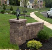
Constructing A Freestanding Wall
The four Cambridge MaytRx® stones (A, B, X, and Y) can be used to build a freestanding wall with a solid face on both sides. By randomly placing the five face sizes available on the four stones, finished walls will have an attractive free style appearance. Another variation may be added by placing capstones on end as a soldier that spans two layers (12") of the wall. With the capstone protruding 1/2" off the face of the wall, this design approach will provide a break in the random pattern while adding a 3D effect.
Stones are easily placed using the alignment groove that visually matches up the next stone in line. Freestanding projects can be built on compacted aggregate or a poured concrete footing. It is important to make sure that the wall is plumb. The wall can be strengthened further by adopting a serpentine design or by incorporating 90-degree corners or columns. Complete the installation with capstones.
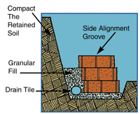
Constructing A Landscape Retaining Wall
When installing a landscape retaining wall, excavate a trench approximately 16 inches wide. Walls of 3 feet in height require a trench depth of at least 6 inches and at least 3 inches of compacted quarry process. Three feet is the maximum recommended height. Dig to virgin soil or compact the soil below your footing to high density. Next compact and level your footing material. Place the first course of Cambridge MaytRx® stones smooth side down. Use a carpenter’s level in all directions and a string line to verify straightness. Use the side alignment groove and line up additional courses to achieve a 3/4" setback, staggering the face seems for interlocking wall strength. Compact a backfill of 3/4-inch stone behind wall. Complete the installation with capstones.
Constructing Engineered SRW Walls
With the use of MaytRx® pins and geogrid, engineered walls may be built up to any height or length with the proper-engineered design.
For information on other installations such as steps and columns using Cambridge MaytRx, visit your Authorized Cambridge Distributor.
Cambridge MaytRx Column
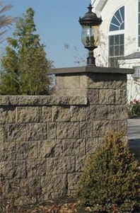 |
Installation Guidelines: Cambridge MaytRx® Column
Columns that are larger than the standard 20 inch by 20 inch MaytRx column can be built as shown by this 36 inch by 36 inch column. Cutting of some MaytRx stones may be required to develop a perfect fit. Each layer’s construction should start at the four corners of these larger columns by using a split A, B or Y part and building away from the corner. To complete each layer, full MaytRx or cut MaytRx stones are then set between the corner stones to finish each side of each layer. Paver grade adhesive is advised in the construction of all columns. Columns may be square as shown or rectangular as required by the job.
 |
 |
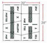
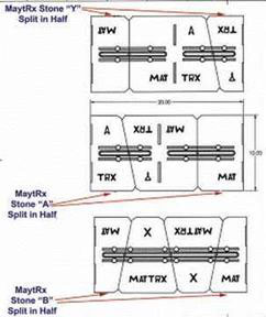 Maytrx
Column Basics
Maytrx
Column BasicsThe multi-stone MaytRx system can build impressive 20 inch square columns and posts. The following drawings show three groupings of MaytRx stones to make 1/2 of a column layer. (i.e. 10 inches by 20 inches)
Combining any two of these three groupings will make one layer of a MaytRx column or post, as shown below.
Rotating layers 90 degrees gives a crossing of the seams of the MaytRx stones for interlock and stability.
Any combination of the 10 inch by 20 inch segments can be used for various layers as a column or post is built. The 90 degree rotation and random use of the three segments will give the four sides of the column or post a random pattern of various stone sizes. Be certain that the column or post is built on a concrete or highly compacted aggregate below grade footing that will hold the column or post plumb for years. Keeping at least 1/2 stone, 3 inches, below grade for the first layer is a proper installation
 |
 |
By adding an additional
dimension of stone on each side, the column will increase from 20''
by that dimension and allow a hollow center for wires. |
 |
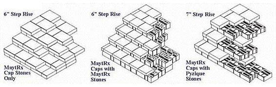
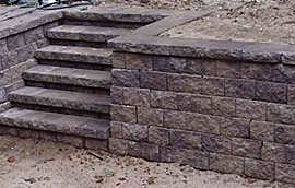
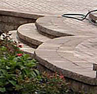
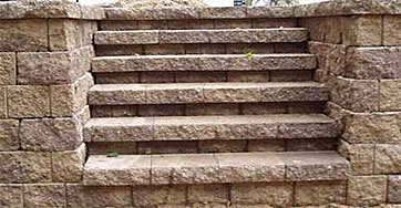
Cambridge MaytRx Stairs
Installation Guidelines: Cambridge MaytRx® Stairs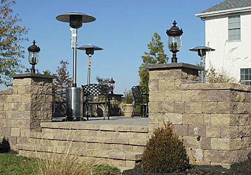 |
MaytRx steps may be built using only MaytRx stones or MaytRx stones and Pyzique stones. There are many options that offer different step riser heights and appearances. Shown here are three different construction options that can be built. The rise of each tread is given with each step drawing. |
 |
| Steps can be built as an integral part
of a retaining wall. Or steps may be built along the side and between
retaining walls. |
 The
use of paver grade adhesive to secure the layers of stones in each
step is advised. Glue all stones with paver grade adhesive using two
to four silver dollar size dollops of glue to secure stones together.
Overlapping layers of capstones in step construction is important
for long term strength and stability of MaytRx steps. Stones may be
glued on the sides for additional strength. The
use of paver grade adhesive to secure the layers of stones in each
step is advised. Glue all stones with paver grade adhesive using two
to four silver dollar size dollops of glue to secure stones together.
Overlapping layers of capstones in step construction is important
for long term strength and stability of MaytRx steps. Stones may be
glued on the sides for additional strength. |
  |
 |
Cambridge Pyzique Retaining and Freestanding Walls
Installation Guidelines: Cambridge Pyzique® Wall Systems
Retaining Walls
Excavate a trench approximately 14 inches wide. Refer to chart below for trench depth.
| Wall Height | Trench Depth |
| 3' | 6" |
| 2' | 4" |
| 1' | 2" |
Compact bottom until fairly level. If you are building on unlevel areas you can prepare step-downs in increments of the 4" thickness of the Pyzique stone. Add 1" of coarse C-33 sand into the bottom of the trench.
The First Course
Place the first layer of Pyzique stones smooth side down on the prepared foundation. Use a carpenter's level in all directions and use a string line to verify straightness. Serpentine walls may be built too. Be certain the base course is level and stones lay flat. For micro leveling and to help the stones lay flat, keep a bag of sand handy and use small handfuls to level and stabilize the first course.
Setback Alignments
Set the center side alignment groove directly above the backmost 5/8" set back groove of the stones in the next lower layer. This visual alignment is all that is required for each successive layer of stones. To prevent any granular fill or soil from passing through the system, a landscaping fabric can be placed behind the wall units. A flexible drain tube is a competent way to assure drainage from behind your wall. As successive layers are set, stagger the face seams of the stones for interlocking wall strength.
Top Cap Row
The normal bottom of each Pyzique stone is smooth. Place the bottom up for your cap row. To avoid vandalism, you may want to use a paver grade glue to secure the cap layer to the layer below it. Place a dab of glue on each of the stones that the cap layer's stone will set on. Stones must be clean and dry for adhesive to bond.
Making A Square Corner
 |
 |
Pyzique can make square corners by splitting one stone from front to back through the middle. Use paver adhesive at each "X" (see illustration). Alternate Row "A" with Row "B" allowing for setback in both directions.
Note: Retaining walls are not built straight up unless expensive geogrid materials and structural deadmen are utilized. Walls must have a horizontal force equal to or greater than the horizontal force of the soil being retained, otherwise the wall will fail. Pyzique is designed with a 5/8" set back for each row (5/8" horizontal tilt per 4" of wall height) to impose a horizontal force against the retained soil.
Tri-Face Option

Simply place a stone chisel in the corner tri-face groove of the face that will be exposed. One hit with the hammer on the chisel at each corner will create the tri-face option.
Free Standing Stone Fences, Patio Barriers & Sitting Walls
Pyzique's patented double split face allows you to build stone fences, patio barriers and sitting walls with both sides showing a beautiful stone finish.
These projects are built straight up using the zero set back groove. Footings must be highly compacted aggregate or solid reinforced concrete. The use of paver adhesive between the upper layers is necessary. Stone fences must be built plumb.
Use construction techniques on these projects similar to those used building a retaining wall. Start your project with at least one layer of stones below the grade. Drain water away from the footing using a drain tile similar to retaining walls. Be certain that stones are level in all directions. Stagger seams of Pyzique stones in these projects and glue the top 2 or 3 layers together for barrier or fence integrity.
Serpentine barriers or stone fences will have greater strength than straight walls. Pyzique stones may need to be cut with a paver chopper or masonry wet saw to achieve specific radii.
For detailed installation instructions on Pyzique Tiered Retaining Walls, Tree Rings, Steps, Lawn, Garden and Paver Borders, visit Your Authorized Cambridge Distributor.
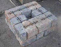
Cambridge Pyzique Bar-B-Que Grill
Pyzique Bar-B-Que Installation Instructions- Choose and level the desired area for your BBQ
- Set aside 28 stones that have a straight or concaved inside face to be used later
- Place 14 stones down to form a complete circle (Start with the stones separated to create a larger diameter. Then push them in towards the center to create a tight fit. A rubber mallet works well for this)
- Check to ensure that the first course is level
- Begin placing the next course (Be sure to offset the stones so you do not have a straight seam)
- For the sixth and seventh layer use the 28 stones that you previously set aside (This will ensure that the insert will fit properly)
- Place the sixth and seventh layers with the stones slightly separated to allow clearance for the BBQ insert
BE SURE THE STONES FORMING THE SEVENTH LAYER HAVE THE
SMOOTH SIDE FACING UP
- Lower the BBQ insert into position
- Push the sixth and seventh layers in to create a tight fit around the insert
- Back fill the BBQ with a suitable material (i.e. sand, rock, etc.) to the bottom of the insert